ESP32-WROVER-E
WROVER module · based on ESP32 (ESP32 (classic)) · Active
- Xtensa LX6
- 2× @ 240 MHz
- Wi-Fi 4
- BT Classic + BLE
- 4 / 8 / 16 MB flash
- 2 / 8 MB PSRAM
- 24 GPIO
- PCB antenna
As an affiliate we may earn from qualifying purchases. Prices and availability are set by AliExpress.
Interactive 3D model · drag to rotate
Figures here are compiled from Espressif's official datasheets, with the source linked on each page. Mistakes are possible, so if something looks off, please report it.
The ESP32-WROVER-E is a PSRAM-equipped Espressif module built on the ESP32 dual-core Xtensa LX6 SoC clocked up to 240 MHz. It pairs 2.4 GHz Wi-Fi 4 and Bluetooth Classic + LE with up to 16 MB flash and up to 8 MB PSRAM, routes the radio to a PCB antenna, and breaks out 24 GPIO; the module measures 18 × 31.4 × 3.3 mm.
The extra PSRAM gives headroom for framebuffers, audio buffers and richer touch GUIs. Secure boot and flash encryption are available for production security. Espressif lists target uses including Smart Home, Audio Devices, Industrial Automation, Generic Low-power IoT Sensor Hubs and Health Care.
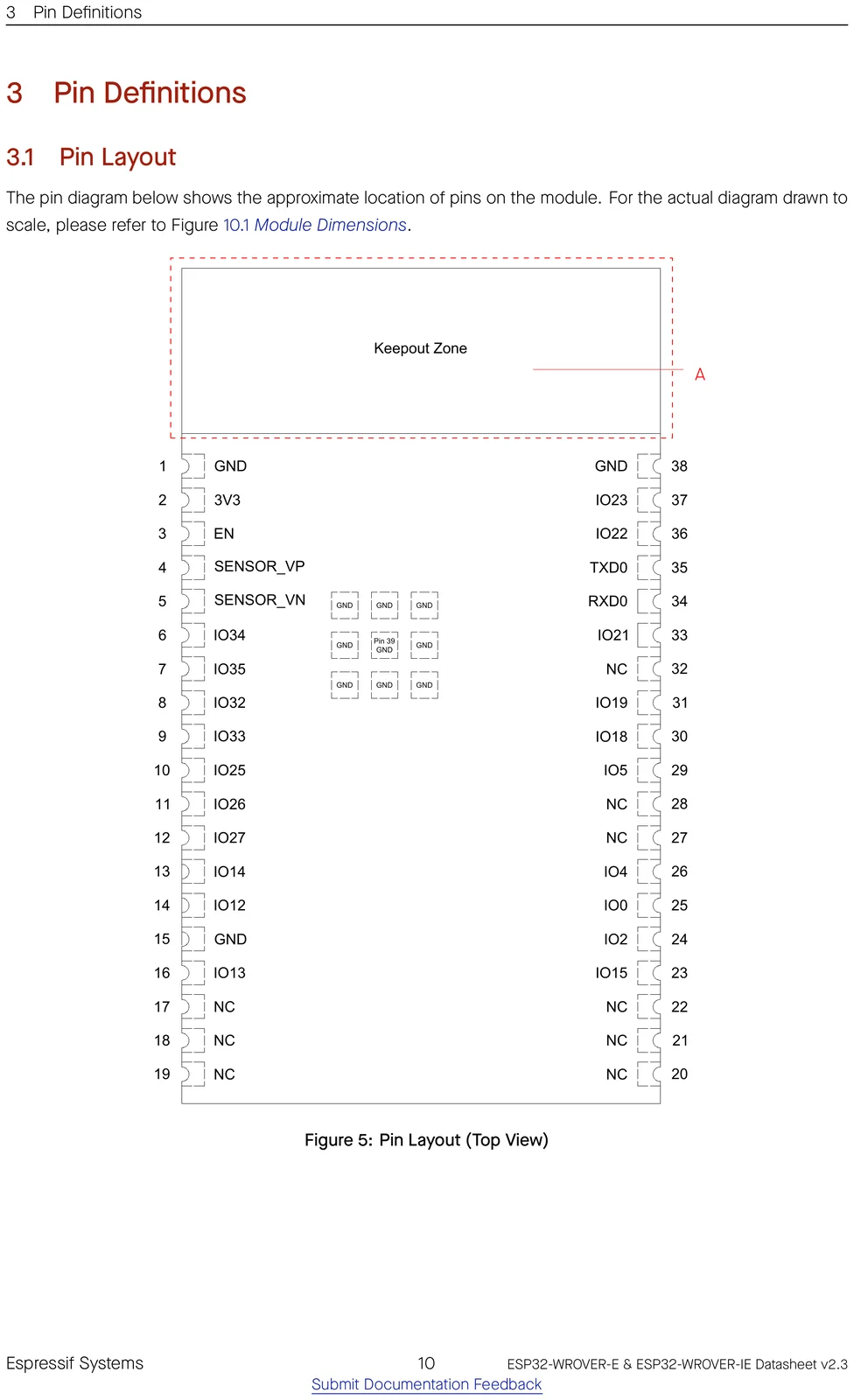
Pinout
⚑ flag an error| # | Name | Type | Functions | |
|---|---|---|---|---|
| 1 | GND | P | Ground | ⚑ |
| 2 | 3V3 | P | Power supply | ⚑ |
| 3 | EN | I | Chip enable | ⚑ |
| 4 | SENSOR_VP | I | GPIO36, ADC1_CH0, RTC_GPIO0 | ⚑ |
| 5 | SENSOR_VN | I | GPIO39, ADC1_CH3, RTC_GPIO3 | ⚑ |
| 6 | IO34 | I | GPIO34, ADC1_CH6, RTC_GPIO4 | ⚑ |
| 7 | IO35 | I | GPIO35, ADC1_CH7, RTC_GPIO5 | ⚑ |
| 8 | IO32 | I/O | GPIO32, XTAL_32K_P (32.768 kHz crystal oscillator input), ADC1_CH4, TOUCH9, RTC_GPIO9 | ⚑ |
| 9 | IO33 | I/O | GPIO33, XTAL_32K_N (32.768 kHz crystal oscillator output), ADC1_CH5, TOUCH8, RTC_GPIO8 | ⚑ |
| 10 | IO25 | I/O | GPIO25, DAC_1, ADC2_CH8, RTC_GPIO6, EMAC_RXD0 | ⚑ |
| 11 | IO26 | I/O | GPIO26, DAC_2, ADC2_CH9, RTC_GPIO7, EMAC_RXD1 | ⚑ |
| 12 | IO27 | I/O | GPIO27, ADC2_CH7, TOUCH7, RTC_GPIO17, EMAC_RX_DV | ⚑ |
| 13 | IO14 | I/O | GPIO14, ADC2_CH6, TOUCH6, RTC_GPIO16, MTMS, HSPICLK, HS2_CLK, SD_CLK, EMAC_TXD2 | ⚑ |
| 14 | IO12 | I/O | GPIO12, ADC2_CH5, TOUCH5, RTC_GPIO15, MTDI, HSPIQ, HS2_DATA2, SD_DATA2, EMAC_TXD3 | ⚑ |
| 15 | GND | P | Ground | ⚑ |
| 16 | IO13 | I/O | GPIO13, ADC2_CH4, TOUCH4, RTC_GPIO14, MTCK, HSPID, HS2_DATA3, SD_DATA3, EMAC_RX_ER | ⚑ |
| 17 | NC | - | See note 2 | ⚑ |
| 18 | NC | - | See note 2 | ⚑ |
| 19 | NC | - | See note 2 | ⚑ |
| 20 | NC | - | See note 2 | ⚑ |
| 21 | NC | - | See note 2 | ⚑ |
| 22 | NC | - | See note 2 | ⚑ |
| 23 | IO15 | I/O | GPIO15, ADC2_CH3, TOUCH3, MTDO, HSPICS0, RTC_GPIO13, HS2_CMD, SD_CMD, EMAC_RXD3 | ⚑ |
| 24 | IO2 | I/O | GPIO2, ADC2_CH2, TOUCH2, RTC_GPIO12, HSPIWP, HS2_DATA0, SD_DATA0 | ⚑ |
| 25 | IO0 | I/O | GPIO0, ADC2_CH1, TOUCH1, RTC_GPIO11, CLK_OUT1, EMAC_TX_CLK | ⚑ |
| 26 | IO4 | I/O | GPIO4, ADC2_CH0, TOUCH0, RTC_GPIO10, HSPIHD, HS2_DATA1, SD_DATA1, EMAC_TX_ER | ⚑ |
| 27 | NC | - | - | ⚑ |
| 28 | NC | - | - | ⚑ |
| 29 | IO5 | I/O | GPIO5, VSPICS0, HS1_DATA6, EMAC_RX_CLK | ⚑ |
| 30 | IO18 | I/O | GPIO18, VSPICLK, HS1_DATA7 | ⚑ |
| 31 | IO19 | I/O | GPIO19, VSPIQ, U0CTS, EMAC_TXD0 | ⚑ |
| 32 | NC | - | - | ⚑ |
| 33 | IO21 | I/O | GPIO21, VSPIHD, EMAC_TX_EN | ⚑ |
| 34 | RXD0 | I/O | GPIO3, U0RXD, CLK_OUT2 | ⚑ |
| 35 | TXD0 | I/O | GPIO1, U0TXD, CLK_OUT3, EMAC_RXD2 | ⚑ |
| 36 | IO22 | I/O | GPIO22, VSPIWP, U0RTS, EMAC_TXD1 | ⚑ |
| 37 | IO23 | I/O | GPIO23, VSPID, HS1_STROBE | ⚑ |
| 38 | GND | P | Ground | ⚑ |
Official datasheet pin-layout figure
Find a pin by function
Pick a capability to see which GPIOs provide it on the ESP32.
Freely usable, no special role.
! Usable for general IO, but one function has a condition (e.g. ADC2 can't be read while Wi-Fi is on). See the note.
UART, I²C, SPI (master), I²S, PWM/LEDC and most digital peripherals route through the GPIO matrix, so assign them to any pin from "Safe GPIO". The categories above are the pins tied to a fixed function (analog, USB, crystal…) or that need care.
Strapping pins
⚑ flag an errorGPIOs sampled at reset; avoid driving these at power-up.
| Pin | Default | Bit | Function |
|---|---|---|---|
GPIO0 | pull-up | 1 | boot_mode |
GPIO2 | pull-down | 0 | boot |
MTDI | pull-down | 0 | flash_voltage |
MTDO | pull-up | 1 | rom_log |
GPIO5 | pull-up | 1 | sdio_timing |
GPIO pin warnings
⚑ flag an errorOn the ESP32, almost any peripheral can be routed to almost any GPIO through the IO MUX, so most pins are free to use. These are the exceptions: pins with a fixed role or a boot-time behaviour to design around.
| Pin | Why it needs care |
|---|---|
GPIO0 | strapping pin (affects boot) |
GPIO1 | UART0 console (boot log) |
GPIO2 | strapping pin (affects boot) |
GPIO3 | UART0 console (boot log) |
GPIO5 | strapping pin (affects boot) |
GPIO12 | strapping pin (affects boot); JTAG |
GPIO13 | JTAG |
GPIO14 | JTAG |
GPIO15 | strapping pin (affects boot); JTAG |
GPIO34 | input-only (no output/pull-up) |
GPIO35 | input-only (no output/pull-up) |
GPIO36 | input-only (no output/pull-up) |
GPIO39 | input-only (no output/pull-up) |
- The ADC2 channels share hardware with the Wi-Fi radio, so ADC2 readings are unavailable while Wi-Fi is active. Those GPIOs are still free for any digital function, and the ADC1 channels work for analog input alongside Wi-Fi.
Compute & memory
⚑ flag an error| CPU | Xtensa LX6, 2-core |
|---|---|
| Max clock | 240 MHz |
| SRAM | 520 KB |
| ROM | 448 KB |
| Flash options | 4 / 8 / 16 MB |
| PSRAM | 2 / 8 MB (quad) |
| Co-processor | ULP-FSM |
Wireless
⚑ flag an error| Wi-Fi | Wi-Fi 4 |
|---|---|
| Wi-Fi bands | 2.4GHz |
| Bluetooth | BT Classic + BLE |
| 802.15.4 (Thread/Zigbee) | No |
| Antenna | PCB |
Peripherals & I/O
⚑ flag an error| Usable GPIO | 24 |
|---|---|
| ADC | 18× 12-bit |
| USB | USB-Serial(external) |
| UART / SPI / I²C / I²S | 3 / 2 / 2 / 2 |
| TWAI (CAN) | Yes |
| SD/MMC | Yes |
| Ethernet MAC | Yes |
| Touch | 10 |
Power
⚑ flag an error| Operating voltage | 3.0-3.6 V |
|---|---|
| Deep sleep | 10 µA |
Physical
⚑ flag an error| Dimensions | 18 × 31.4 × 3.3 mm |
|---|---|
| Pin count | 38 |
| Temp range | -40 to 85 °C |
| Mounting | SMD castellated |
| Lifecycle | Active |
Security
⚑ flag an error| Secure boot | Yes |
|---|---|
| Flash encryption | Yes |
| Crypto | AES, SHA, RSA, RNG |
| Digital signature | No |
| TRNG | Yes |
Ordering codes
⚑ flag an errorThe orderable part numbers and what each ships with, decoded from the suffix. Confirm against the latest datasheet before ordering.
| Part number | Flash | PSRAM | Temp |
|---|---|---|---|
ESP32-WROVER-E-N4R8 | 4 MB | 8 MB (octal) | −40 to 85 °C |
ESP32-WROVER-E-N8R8 | 8 MB | 8 MB (octal) | −40 to 85 °C |
ESP32-WROVER-E-N16R8 | 16 MB | 8 MB (octal) | −40 to 85 °C |
ESP32-WROVER-E-N4R2 | 4 MB | 2 MB (quad) | −40 to 85 °C |
ESP32-WROVER-E-N8R2 | 8 MB | 2 MB (quad) | −40 to 85 °C |
ESP32-WROVER-E-N16R2 | 16 MB | 2 MB (quad) | −40 to 85 °C |
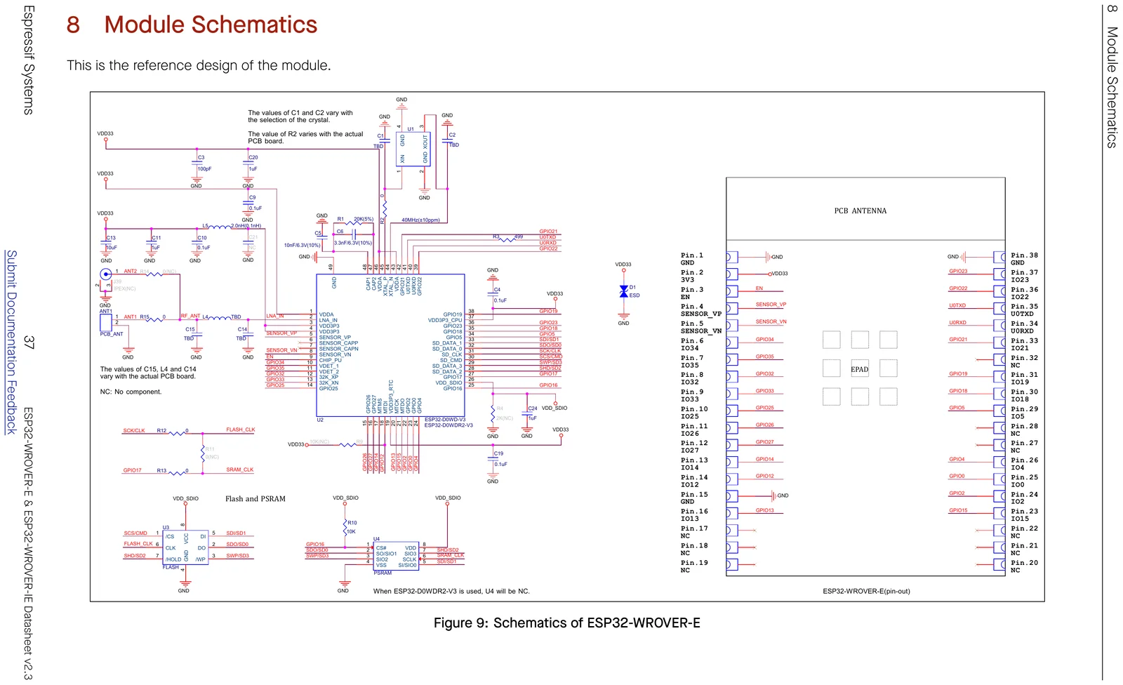
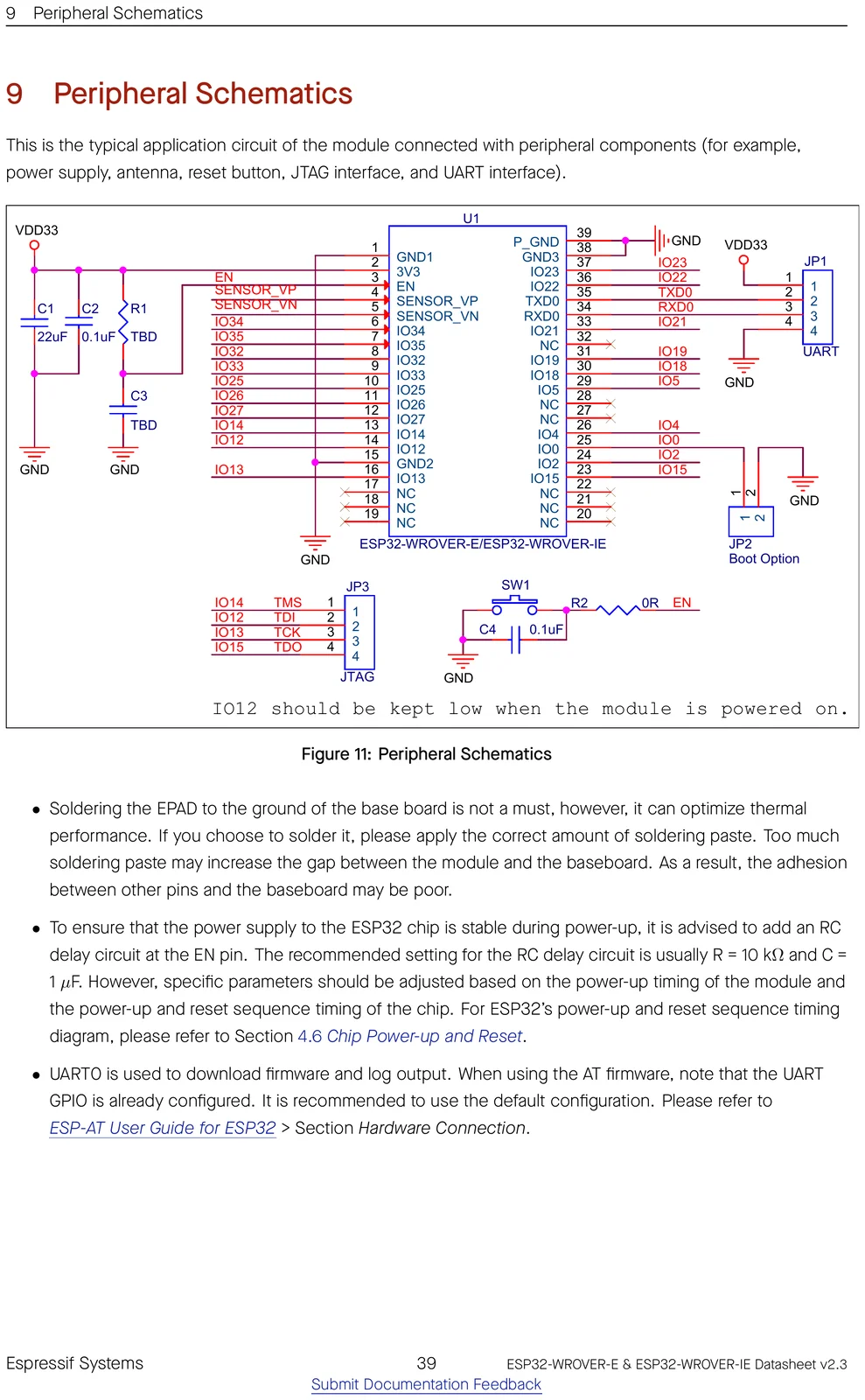
Schematics
Mechanical & CAD

Getting started
Frameworks: Arduino-ESP32 core (fully supported) · ESP-IDF 3.0+ (Espressif's official SDK) · MicroPython.
ESP-IDF target: idf.py set-target esp32.
Programming uses UART. Most dev boards include a USB-to-UART bridge; for the bare module add your own (e.g. CP2102/CH340).
Software & firmware
⚑ flag an errorPopular firmware and SDKs that run on the ESP32, so they run on the ESP32-WROVER-E too.
Notable open-source software & firmware known to run on this chip. Support evolves, so check each project for its current board support.
Smart home & IoT
- Tasmota★ 24k
Mature open firmware for smart switches, plugs and sensors, with web UI, MQTT and rules.
- ESPHome★ 11k
Describe your device in YAML and get firmware that integrates straight into Home Assistant, no C required.
- OpenMQTTGateway★ 4.0k
Bridges BLE, 433 MHz, IR and more to MQTT; a flexible multi-protocol IoT gateway.
- ESPresense★ 1.4k
Turn ESP32 nodes into a room-level BLE presence-detection network for Home Assistant.
SDKs & languages
- MicroPython★ 22k
Run Python 3 directly on the chip with an interactive REPL, great for rapid prototyping.
- ESP-IDF★ 18k
Espressif's official IoT development framework (FreeRTOS-based, C/C++); the reference SDK for every modern ESP32-family chip.
- Arduino-ESP32★ 17k
The official Arduino core for ESP32 chips; the easiest on-ramp, built on top of ESP-IDF.
- NodeMCU firmware★ 7.9k
Lua-scriptable firmware that made the ESP8266 famous; an ESP32 port is also available.
- esp-hal (esp-rs)★ 2.0k
Bare-metal Rust hardware-abstraction layer for Espressif chips, and the heart of the esp-rs ecosystem.
LED, display & UI
Security research
- ESP32 Marauder★ 11k
Wi-Fi/Bluetooth analysis and pen-testing suite for ESP32, for authorised testing and education.
- Bruce★ 5.8k
Predatory ESP32 firmware for offensive-security research on M5Stack and cheap-yellow-display boards.
Mesh & comms
- Meshtastic★ 7.8k
Long-range, off-grid LoRa mesh messaging firmware for ESP32-based radios.
AI, vision & voice
- ESP-WHO★ 2.1k
Espressif's on-device image-recognition framework (face detection/recognition) for camera builds.
Open-source projects using this module
Public GitHub projects whose KiCad design files reference the ESP32-WROVER-E.
- DavidVentura/PicoPico ★ 127
Pico-8 Player
- martinroger/ipodesp32 ★ 20
An iPod emulator for 2006-2013 BMW Mini Coopers that need Bluetooth
Frequently asked questions
Does the ESP32-WROVER-E have Wi-Fi and Bluetooth?
It provides 2.4 GHz Wi-Fi 4 and Bluetooth Classic + LE.
How much memory does the ESP32-WROVER-E have?
It comes with 4, 8, 16 MB flash options, up to 8 MB of PSRAM, and the ESP32 has 520 KB of on-chip SRAM.
How many GPIO pins does the ESP32-WROVER-E have?
The module breaks out 24 GPIO, with up to 18 12-bit ADC channels. See the full pinout above.
Can I use the ESP32-WROVER-E with the Arduino IDE?
Yes. Install the Arduino-ESP32 core and pick an ESP32-based board. You can also use ESP-IDF 3.0 or MicroPython.
How do I flash the ESP32-WROVER-E?
Programming uses UART. Most dev boards include a USB-to-UART bridge; for the bare module add your own (e.g. CP2102/CH340).
Is the ESP32-WROVER-E 5 V tolerant?
No. It runs at 3.0-3.6 V and its GPIO are not 5 V tolerant, so level-shift any 5 V signals.
Can I use an external antenna with the ESP32-WROVER-E?
Most Espressif modules are also offered in a "-U" / "-1U" variant that swaps the on-board PCB antenna for a U.FL/IPEX connector, otherwise identical. Check this part's datasheet for the exact variant name.